 |
| What's Hot! | Products/ Tools | EFI Tuning | Basic Tuning | Advanced Tuning | Chassis Tuning | Advertise with us |
CATEGORIES FOR ARTICLE LINKS BELOW
![]()
DOT Help |
Car Engine Crankcase Ventilation System
With Permission from: BenFenner link
While this article will use a Nissan SR20 engine as a reference, the information found here can be applied to all motors.
If you're reading this you've likely asked a question about crank case ventilation, catch can placement, correct PCV hose routing, or similar. Grab yourself a beverage of your choice, sit back and relax. Keep reading to have all of your questions answered. To understand what you're doing when you modify or repair the factory crank case ventilation system you should know how the factory systems works first before diving into modifying it or fixing it. It might also be nice to understand the history and evolution of the crank case ventilation system, so I'm going to start with the early SR20DE system and work up from there.
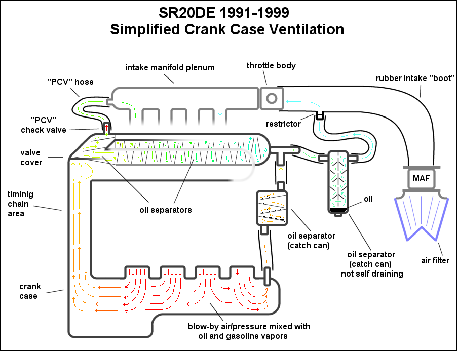
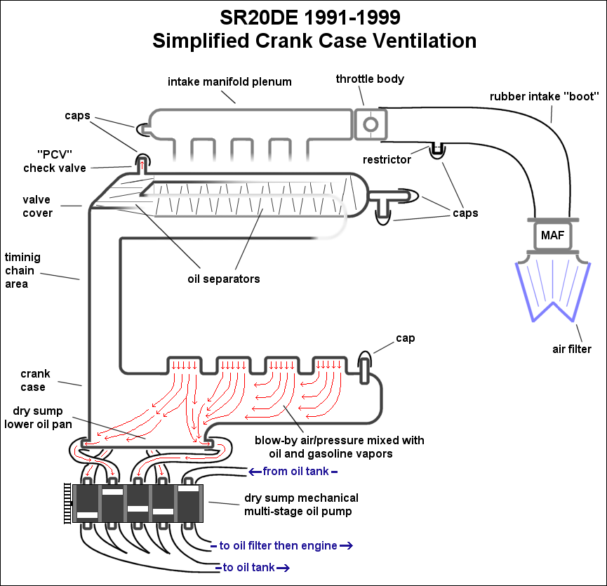
I know people like images so I won't hold off any longer. Here's the factory system (click image for larger display):
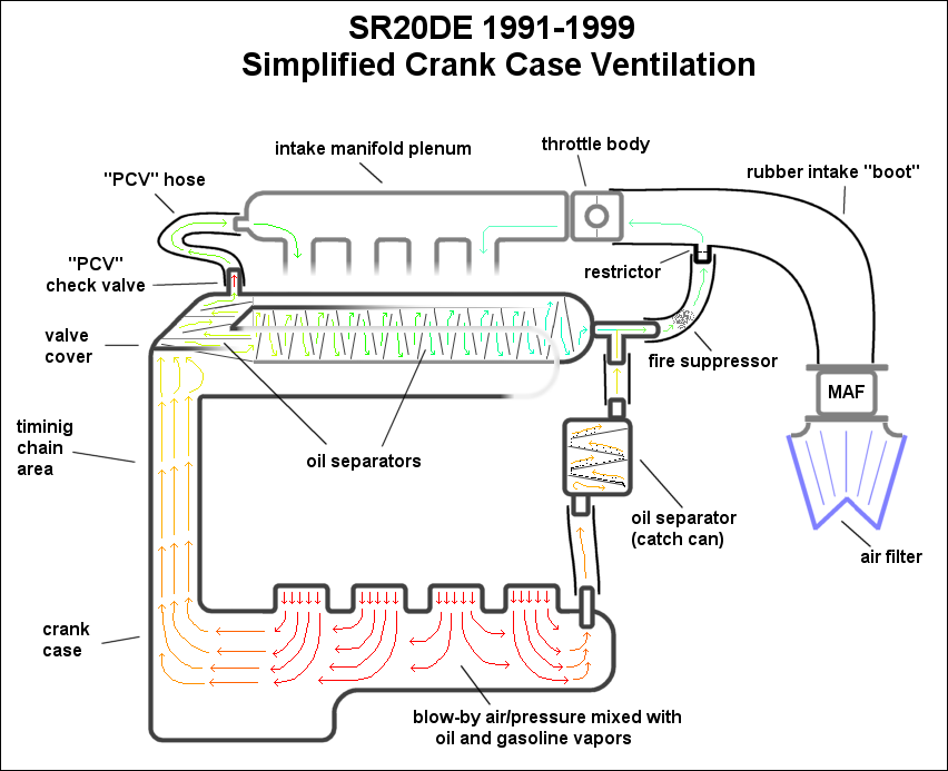
Now let me explain what's happening here. The piston rings don't seal perfectly, so there is some air that gets by them and we call that blow-by. This blow-by air is pressurized and will cause oil seals to fail and eventually will cause other major problems so it needs to be dealt with. Having a vacuum in the crank case is very good as it promotes ring seal and keeps windage losses (drag on the rotating crank caused by a cloud of oil in the crank case) to a minimum.
Since having a vacuum in the crank case is good and having pressure there is bad, we must get rid of the pressure somehow. The air comes in contact with a lot of oil in the crank case and basically turns into a mix of air and oil (along with a little bit of gasoline and water). This air/oil mix is represented by the red arrows in the crank case and as oil gets removed throughout the system I've made the color shift towards blue. I even showed little oil droplets condensing out of the air as it goes up through the "catch can" oil separator. I didn't show them everywhere in all the baffles, but you can imagine the same thing happening everywhere you see baffles.
The amount of air and oil can be quite significant, so Nissan put in two important pathways for the pressure to escape from the crank case because at times there can be a lot of air to evacuate. On the left the air and oil can escape the crank case up along the timing chain portion of the block and into the valve cover. This is the usual pathway for the air to take. On the right the oily air can escape the crank case (in times where there is excessive pressure to evacuate) through the provision in the side of the block, up through the oil separator (catch can) leaving the crank case.
So the goal is to have a vacuum in the crank case, and this is accomplished on some vehicles with a dry sump oil system, but on regular vehicles the intake manifold is used for the source of vacuum. Basically the engine is setup to consume it's own blow-by gasses. Not a super great idea, but certainly efficient, practical, and good for the environment. All right if you've been paying attention we now have the blow-by gasses up and out of the crank case and in the valve cover now. The gasses are going to continue on through the small PCV (positive crank-case ventilation) port at the top-left corner of the valve cover which includes a one-way check valve so things can only flow out (and not in). The gasses flow out of the PCV port and into the intake manifold where they are sucked back into the engine to get consumed and pushed out of the exhaust. Simple enough. Now the gasses have a bit of oil mixed in with it, so on it's way out of the valve cover it passes through a labyrinth of baffles designed to help condense the oil and collect the oil from the air. The more surface area the oil has to cling on to the more oil will separate from the air. The oil that is collected drains back down onto the valve train and eventually returns to the oil pan.
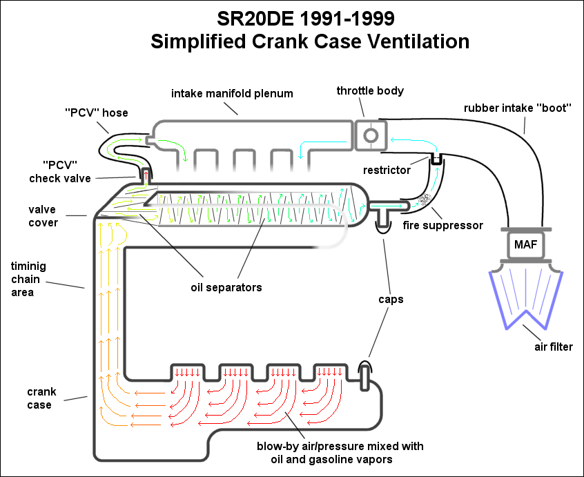
Here is another diagram showing the normal operation of the crank case ventilation system with half of the system greyed out:
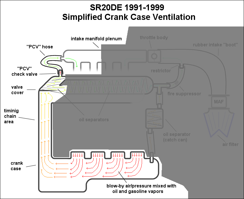
That pathway is used around 90% of the time you drive the car. A little blow-by is pushed into the crank case but the intake manifold sucks it up and the oil separator in the valve cover keeps most of the oil from escaping the engine. The manifold keeps a good vacuum on the crank case during idle and partial throttle conditions which amount to most of your driving.
"Okay Ben, what happens when you're at WOT then?" I'm glad you asked.
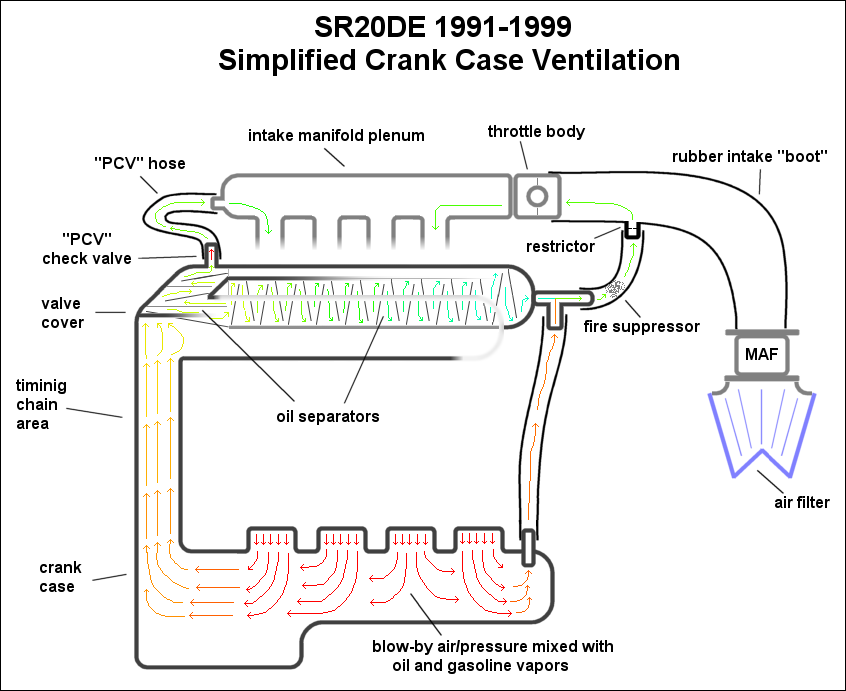
That's where the other half of the system comes into play. Now there are a couple things happening at WOT. Firstly, there is no real vacuum to speak of in the intake manifold or plenum. With the throttle fully open, the entire intake track experiences atmospheric pressure and no longer produces any vacuum. This means there won't be any vacuum applied to the crank case and blow-by evacuation will be problematic. Secondly, WOT produces the most blow-by because of the pressure in the cylinder and the lack of vacuum in the crank case (remember the vacuum promotes ring seal and without good ring seal there is more blow-by). This means there is a lot more blow-by to deal with at WOT and there's no vacuum to suck the blow-by up.
In the past, OEMs just vented the crank case to atmosphere and called it a day. In these times of pollution consciousnesses, spouting air with oil and gasoline vapors into the atmosphere untreated is a big no-no. So in an effort to control those emissions Nissan routed the gasses back into the intake to take advantage of the slight vacuum present in the intake (very slight) and also route the pollutants back into the engine to be consumed and eventually treated by the catalytic converter. Because there is not really any vacuum present, the blow-by gasses build up pressure and relatively slowly move up to the valve cover via both the left and right pathways. These pathways are also larger than the regular PCV hose because flow is important now that the vacuum is gone. Let's follow the path of the blow-bay gasses at WOT.
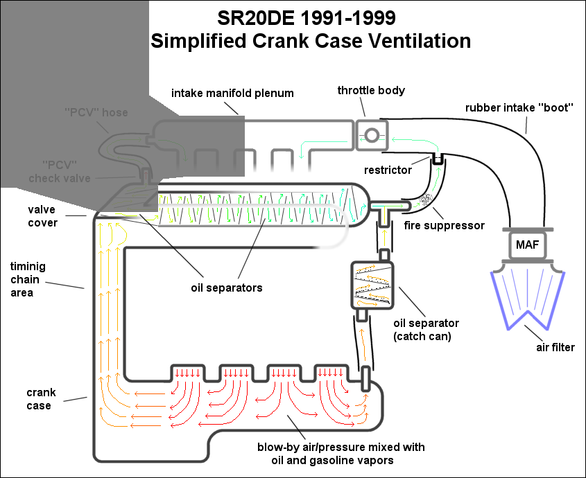
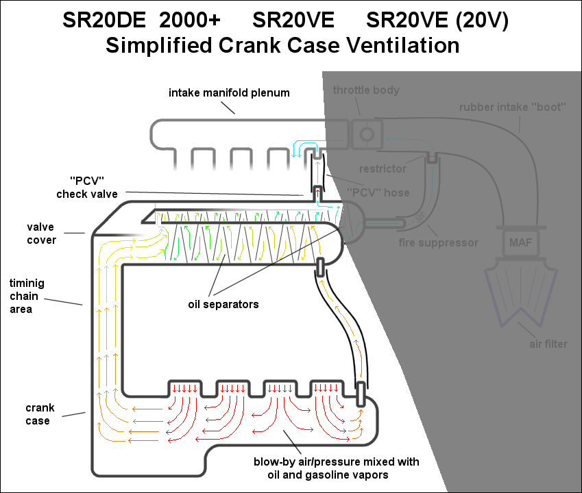
They start out at the bottom just as before and this time they go up the timing chain section and the catch can section on the right. The pressure in the crank case is now going to be about equal to that in the intake manifold, so not much of anything will flow through the PCV hose. The blow-by gasses will have to continue on through the valve cover where there is even more built-in oil separation labyrinth. Eventually the gasses leave the valve cover and meet up with the gasses that took the other route through the catch can. By now both routes have gone through an oil separator so the air is going to be relatively oil free. Here is another diagram showing this part of the system with the regular section greyed out:
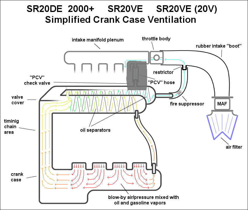
Okay now that we have the basics down the rest should be a lot easier to get through. Nissan basically upgraded the crank case ventilation system when they moved on to the roller rocker head and have kept it generally the same from then on all the way to the SR20VE engines including the N1 and the 20V varieties. They basically did two things when they upgraded the system. They got rid of the stand-alone oil separator (catch can) and built it into the valve cover. They also moved the "PCV" port from the top-left of the valve cover way over to the right side. This simplified and cleaned up the engine bay by including the oil separator for the right pathway into the valve cover. It also increased the ability for the system to remove oil from the blow-by because of a minor but significant rerouting of the right pathway. I've tried to describe this visually by changing the colors of the arrows as they flow through the system. You should be able to notice that the arrows are more blue in these diagrams than in the ones from the old system. Here's a diagram of the system:
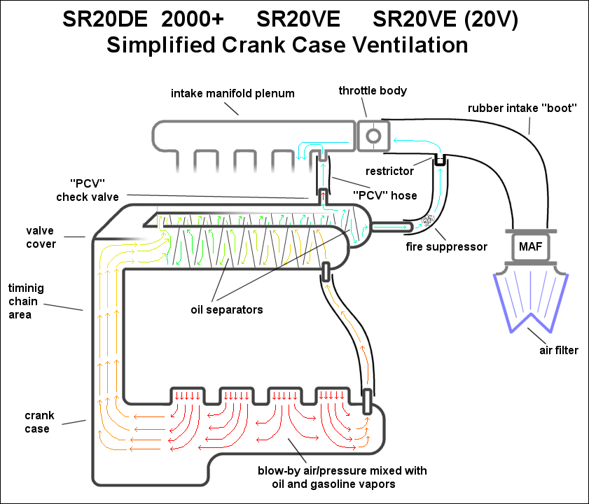
You should notice immediately that the stand-alone catch can is gone now, and that tube connects directly to the forward portion of the valve cover. The new valve cover has an additional oil separation pathway that it didn't have before which serves the purpose of the old stand-alone catch can. You'll also notice right away that the PCV hose has moved way over to the right and blow-by gasses have much farther to travel (through more oil separation labyrinth) before leaving the valve cover. Here is what things look like at idle or partial throttle with the inactive sections greyed out:
Hopefully these diagrams are making sense and looking familiar to you by now. As you can see, the blow-bay gasses are still forced to go through all of the oil separators even though we're at idle or partial throttle. This is not the case in the old system. Now for a look at what happens during WOT:
As before, the PCV hose is taken out of the equation because nothing is going to flow to the manifold now that the pressure in the intake manifold and the valve cover is about the same. Even if some blow-by gasses do go through the PCV hose, there is lots of it left and the other pathway to the intake track is vital to providing a wide enough pipe for the gasses to escape through. That's about all there is to the newer system. It's a step above the old system in many ways that hopefully now you understand quite well.
So now that you know the basics, I'm sure you're wondering what (if anything) can be done to improve the system. Well you certainly won't be alone. Plenty of people want to reduce blow-by, clean up the engine bay, simplify the crank case ventilation system, and prevent every last bit of oil from being sucked into the intake and gumming things up. However the system is a little more complicated than most people think and it's actually well designed from the beginning so it's hard to improve on. As history has shown, this is a hot topic.
Fred Cooke is my Australian brother-from-another-mother and he has his own crank case ventilation (not SR20 specific) explanation thread on his own forum. It is very easy to read and extremely thorough. It's where I finally got a handle on the situation and really helped me a lot in figuring out how it all works. It might be a bit late to link to it now, but here it is anyway: http://www.diyefi.org/forum/viewtopic.php?f=24&t=357
Fred really emphasizes the importance of making sure the system has enough flow. Tube diameter is important and 99% of catch cans on the market actually introduce a huge restriction to the system so you'll want to make sure you keep an eye on that. Really I should make that thread a mandatory read, but oh well.
Okay on to the different methods of improving, or completely messing up the factory crank case ventilation system. These methods will cover a huge mix of things I've seen done on people's cars, or that I thought up in my head. Some will be great ideas, some will be good ideas, some will be bad ideas, and some will be awful ideas. I'm going to keep things simple by rating each method on the important points so you can just give it a quick look and see immediately if it's a good idea or not.
WOT "catch can" elimination on 1991-1999 engines via cap method:
Effect on the following characteristics:
* De-clutters the engine bay - Yes
* Simplifies crank case ventilation system - Yes
* Helps remove more oil from the air - No
* Help evacuate the crank case - No
* Maintains or improves the stock flow capacity - No
* Helps promote ring seal and prevent blow-by - No
* Helps prevent oil smoke in exhaust - No
* Helps prevent dip stick from popping out - No
* Helps prevent oil leaks due to pressure - No
* Helps keep intake track clean including throttle body - No
* Helps keep intake manifold/plenum clean - No
* Maintains or reduces amount of pollutants - Maybe
* Maintains prevention of un-metered air from entering the intake - Yes
Consensus: BAD IDEA
WOT "catch can" elimination on 1991-1999 engines via bypass method:
Effect on the following characteristics:
* De-clutters the engine bay - Yes
* Simplifies crank case ventilation system - Yes
* Helps remove more oil from the air - No
* Help evacuate the crank case - No change
* Maintains or improves the stock flow capacity - No change
* Helps promote ring seal and prevent blow-by - No change
* Helps prevent oil smoke in exhaust - No change
* Helps prevent dip stick from popping out - No change
* Helps prevent oil leaks due to pressure - No change
* Helps keep intake track clean including throttle body - No
* Helps keep intake manifold/plenum clean - No
* Maintains or reduces amount of pollutants - No
* Maintains prevention of un-metered air from entering the intake - Yes
Consensus: BAD IDEA
Venting WOT section to atmosphere on 1991-1999 engines with "breather" filter:

Effect on the following characteristics:
* De-clutters the engine bay - Maybe
* Simplifies crank case ventilation system - Maybe
* Helps remove more oil from the air - No change
* Help evacuate the crank case - No
* Maintains or improves the stock flow capacity - Yes
* Helps promote ring seal and prevent blow-by - No
* Helps prevent oil smoke in exhaust - No
* Helps prevent dip stick from popping out - No
* Helps prevent oil leaks due to pressure - No
* Helps keep intake track clean including throttle body - Yes
* Helps keep intake manifold/plenum clean - Yes
* Maintains or reduces amount of pollutants - No
* Maintains prevention of un-metered air from entering the intake - No
Consensus: BAD IDEA
Adding a "catch can" to the WOT section on 1991-1999 engines:
Effect on the following characteristics:
* De-clutters the engine bay - No
* Simplifies crank case ventilation system - No
* Helps remove more oil from the air - Yes
* Help evacuate the crank case - No change
* Maintains or improves the stock flow capacity - No change
* Helps promote ring seal and prevent blow-by - No change
* Helps prevent oil smoke in exhaust - No change
* Helps prevent dip stick from popping out - No change
* Helps prevent oil leaks due to pressure - No change
* Helps keep intake track clean including throttle body - Yes
* Helps keep intake manifold/plenum clean - Yes
* Maintains or reduces amount of pollutants - Yes
* Maintains prevention of un-metered air from entering the intake - Yes
Consensus: GOOD IDEA
Adding a "catch can" to the PCV section on 1991-1999 engines:
Effect on the following characteristics:
* De-clutters the engine bay - No
* Simplifies crank case ventilation system - No
* Helps remove more oil from the air - Yes
* Help evacuate the crank case - No change
* Maintains or improves the stock flow capacity - No change
* Helps promote ring seal and prevent blow-by - No change
* Helps prevent oil smoke in exhaust - No change
* Helps prevent dip stick from popping out - No change
* Helps prevent oil leaks due to pressure - No change
* Helps keep intake track clean including throttle body - No change
* Helps keep intake manifold/plenum clean - Yes
* Maintains or reduces amount of pollutants - Yes
* Maintains prevention of un-metered air from entering the intake - Yes
Consensus: GOOD IDEA
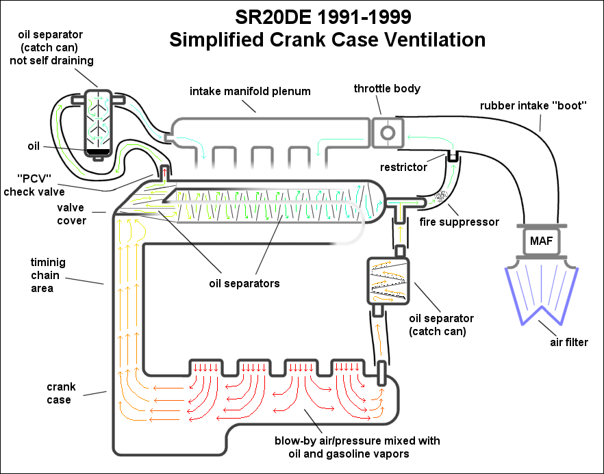
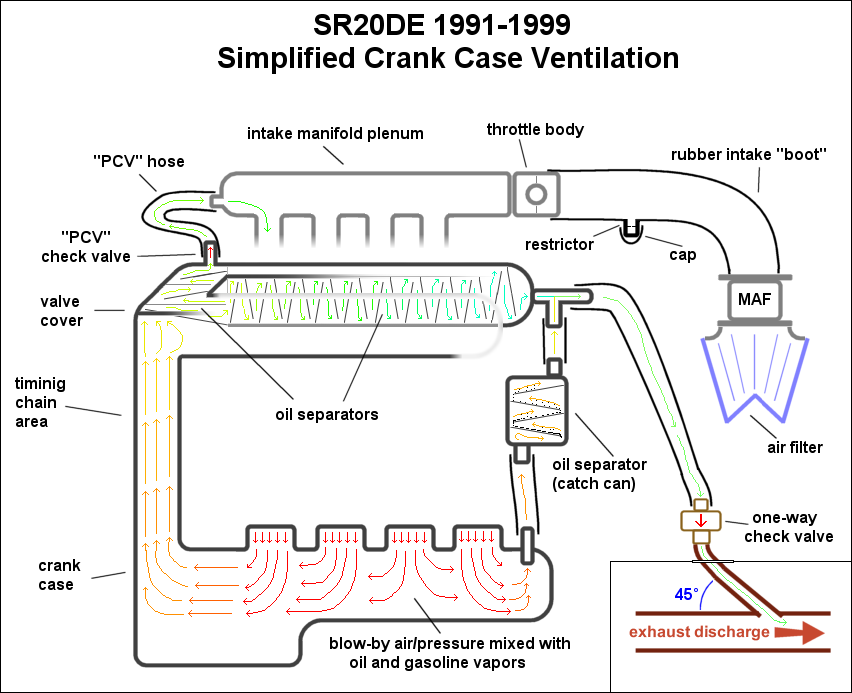
Using the exhaust to create suction (via a venturi) to ventilate the crank case on 1991-1999 engines:
Effect on the following characteristics:
* De-clutters the engine bay - No
* Simplifies crank case ventilation system - No
* Helps remove more oil from the air - No
* Help evacuate the crank case - Yes
* Maintains or improves the stock flow capacity - Yes
* Helps promote ring seal and prevent blow-by - Yes
* Helps prevent oil smoke in exhaust - Yes
* Helps prevent dip stick from popping out - Yes
* Helps prevent oil leaks due to pressure - Yes
* Helps keep intake track clean including throttle body - Yes
* Helps keep intake manifold/plenum clean - Yes
* Maintains or reduces amount of pollutants - No
* Maintains prevention of un-metered air from entering the intake - Yes
Consensus: GOOD IDEA
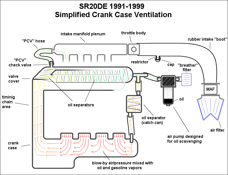
Using an air pump (electric or mechanical) to ventilate the crank case on 1991-1999 engines:
Effect on the following characteristics:
* De-clutters the engine bay - No
* Simplifies crank case ventilation system - No
* Helps remove more oil from the air - Yes
* Help evacuate the crank case - Yes
* Maintains or improves the stock flow capacity - Yes
* Helps promote ring seal and prevent blow-by - Yes
* Helps prevent oil smoke in exhaust - Yes
* Helps prevent dip stick from popping out - Yes
* Helps prevent oil leaks due to pressure - Yes
* Helps keep intake track clean including throttle body - Yes
* Helps keep intake manifold/plenum clean - Yes
* Maintains or reduces amount of pollutants - Yes
* Maintains prevention of un-metered air from entering the intake - Yes
Consensus: GREAT IDEA!
Using a dry sump oiling system to ventilate the crank case on 1991-1999 engines:
Effect on the following characteristics:
* De-clutters the engine bay - Maybe
* Simplifies crank case ventilation system - Yes
* Helps remove more oil from the air - Yes
* Help evacuate the crank case - Yes
* Maintains or improves the stock flow capacity - Yes
* Helps promote ring seal and prevent blow-by - Yes
* Helps prevent oil smoke in exhaust - Yes
* Helps prevent dip stick from popping out - Yes
* Helps prevent oil leaks due to pressure - Yes
* Helps keep intake track clean including throttle body - Yes
* Helps keep intake manifold/plenum clean - Yes
* Maintains or reduces amount of pollutants - Yes
* Maintains prevention of un-metered air from entering the intake - Yes
Consensus: BEST IDEA!!!
Be sure to check out popular oil seperators and catchcans from the link below:
ATTENTION READER:
If you enjoyed the information and article you just read be sure to check out our newly released book with even more exciting photo's and information:How to Turbocharge and Tune your Engine
Want to know more about your particular Make and Model vehicle? All of these vehicles are covered in the tech, maintenance and repair articles found above. Enginebasics is the wiki or wikipedia of car part, repair, how to and tuning information. Let us be the class 101 for your automotive learning.
| Ford | General Motors GM | Pontiac | Jaguar | Land Rover | Nissan |
| Toyota | Honda | Lexus | Acura | Lotus | Scion |
| Infinity | BMW | Mercedes | Mitsubishi | Ferrari | Maserati |
| Lamborghini | Volks Wagen VW | Saab | Audi | Hyundai | Kia |
| Subaru | Mazda | Chevy | Volvo | Caddilac | Dodge |
| Chrylser | Daewoo | Porsche | Mercury | Freightliner | MG |
Individual Models
| Ford Mustang | Mitsubishi Eclipse | Mitsubishi Evo | Subaru WRX / STI | Dodge Viper | Chevrolet Corvette |
| Nissan Skyline | Honda S2000 | Nissan 350z | Toyota Supra | Chevy Camaro | Lotus Elise Exige |
| Honda Civic | VW Golf | Dodge SRT-4 | Eagle Talon | Acura Integra | BMW M3 |
| Nissan 240sx | Porsche 911 | Acura NSX | Honda Accord | Toyota Camry | Toyota MR2 |
| VW R32 | Dodge Truck | Mazda Rx7 | VW Jetta | Sand Buggy | Nissan Sentra |
For the latest Automotive news and stories visit the websites below |


Our feature Build: An AWD V6 Civic